CD4021
The functional NXP diagram is shown in figure 1. There is a DS (serial data in), CP (clock pulse), outputs Q5, Q6 and Q7. And then there are parallel load inputs D0 through D7, with a parallel load signal PL. This screams parallel load of push button data and then shifted out.

The first hunch here is that the CP signal (clock) is shared with the other shift registers. A resistance reading confirms this, so no mystery there. The parallel load (PL) is probably wired up to the strobe signal, since there is only one remaining signal left for the PCB and it has to be for the shifted out data. A meter reading confirms that PL is connected to the strobe input on the board.
The D0 through D7 inputs connect to the pushbuttons and are loaded when the board Strobe goes high. After the Strobe returns low, successive clock pulses (CP) shift out the data (PCB pin 2, green wire).
The only remaining question, which is fairly obvious actually, is where does the shifted out data come from? It has to be be Q7 or else one or more bits would never be seen at the PCB pin 2 output. A simple resistance reading confirms this, if there was any doubt.
So now we have decoded the PCB connections:
- +5 Volts (purple wire)
- Push button data out (green wire)
- Data in (yellow wire)
- Strobe in (red wire)
- Clock pulse in (orange wire)
- Ground (brown wire)
After programming the AVR device (ATmega328P), I was eventually able to drive this board with a few mis-steps. Essentially, with the PCB mod (more about this later), I shift out 25 bits of data and then strobe it. The DLG modules that have the low /WR signal going high, then receive their data. At the same time, the Strobe signal enables any push button LEDs, when in the low state (these are active low). Finally, after the Strobe returns low, a few more clock pulses (CP) return the push button data (the button data is loaded at the high of Strobe). The AVR code can be found here:
Repository: https://github.com/ve3wwg/avr
CD4001 Hack
One major irritation with the PCB was that it limited access to the DLG-1414 character set. The PCB would play games with data bit D6 via IC4a. I tried to find ways to use the PCB unmodified and gave up on that. Since only the first gate is used in IC4, we can just pull the chip out entirely (the board functions without it). By soldering a wire from pin 3 of IC4a to pin 10 (QS2) of IC3 as described in part 3, we arrive at full control of D0 through D6 of the DLG-1414.
The Schematic
I was later reminded that I did in fact have a schematic for this PCB. So let's look at it now (Figure 2), to see how we did.
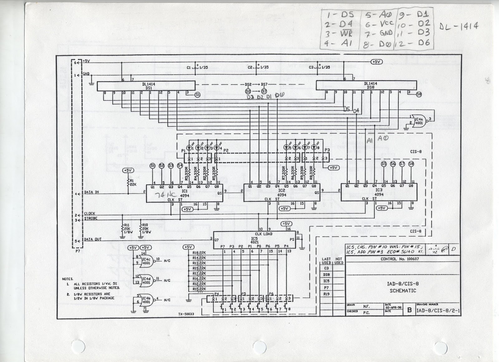 |
| Figure 2. The PCB Schematic |
The first thing I noticed was that they numbered their connections opposite to the way I did mine. Their pin 6 was my pin 1 for +5 Volts. Otherwise, things were fairly accurate.
Their wiring of IC4a was different than mine. As discussed in Part 3, I had a resistor divider, while the schematic shows pin 2 grounded and pin 1 connected to pin 1 of the DLG-1414. With IC4 removed and the mod added, this is all academic now.
My particular PCB also disagreed about the push button wiring. I was required to map the buttons as follows:
struct { // Input order
unsigned pb4 : 1;
unsigned pb3 : 1;
unsigned pb2 : 1;
unsigned pb1 : 1;
unsigned pb7 : 1;
unsigned pb6 : 1;
unsigned pb5 : 1;
unsigned pb0 : 1;
unsigned fill : 8;
} sr;
So there you have it. I hope you enjoyed this little journey down reverse engineering row!
No comments:
Post a Comment